
Zone Damper Wiring Diagrams Explained
A zone damper wiring diagram is a visual guide that shows how the zoning board connects to the motorized dampers in your ductwork. These diagrams are essential for technicians because they show exactly which wires go where and how the dampers should operate.
Understanding these diagrams helps explain why your zoning system behaves the way it does and why professional installation is so important.
Why Zone Damper Wiring Diagrams Matter
Every zoning system is slightly different depending on the brand of dampers, the zoning board, and how many zones your home has. A wiring diagram removes the guesswork by showing:
- Which wires control each damper
- How power is supplied to the damper motors
- Whether the damper is power-open or spring-close
- How the zoning board communicates with each damper
Common Types of Zone Damper Wiring
There are a few standard ways zone dampers are wired. Here are the most common types used in DFW homes:
1. 2-Wire Damper Wiring
This is the simplest type. One wire sends power to open the damper, and the second wire sends power to close it. These systems are less common in modern installations because they require constant power to hold the damper in position.
2. 3-Wire Damper Wiring (Most Common)
This is the standard setup used by most major zoning brands. It includes:
- One common wire (usually white or blue)
- One wire for the “open” position
- One wire for the “close” position
| 1. 2-Wire Damper (Constant Power) |
|---|
|
[Zone Board] — Wire 1: 24V to Open → [Motor] (Requires power to hold open) [Zone Board] — Wire 2: 24V to Close → [Motor] (Requires power to hold closed) |
| 2. 3-Wire Damper (Most Common) |
|
[Zone Board] — Wire 1: Common → [Motor] [Zone Board] — Wire 2: 24V to Open → [Motor] (Turns open, then stops) [Zone Board] — Wire 3: 24V to Close → [Motor] (Turns closed, then stops) |
| 3. Power-Open / Spring-Close (Most Popular) |
|
[Zone Board] — Wire 1: 24V Power → [Motor] (Powers open against spring) [Zone Board] — Wire 2: Common → [Motor] * When power is cut, mechanical spring auto-closes blade |
These dampers use a small motor that moves the damper blade to the open or closed position and then stops.
3. Power-Open / Spring-Close Wiring
This is currently the most popular type in residential zoning. When the zoning board sends power to the damper, it opens. When power is removed, a spring automatically closes the damper. This design is more reliable and uses less electricity.
How to Read a Basic Zone Damper Wiring Diagram
Most zone damper wiring diagrams follow a similar layout:
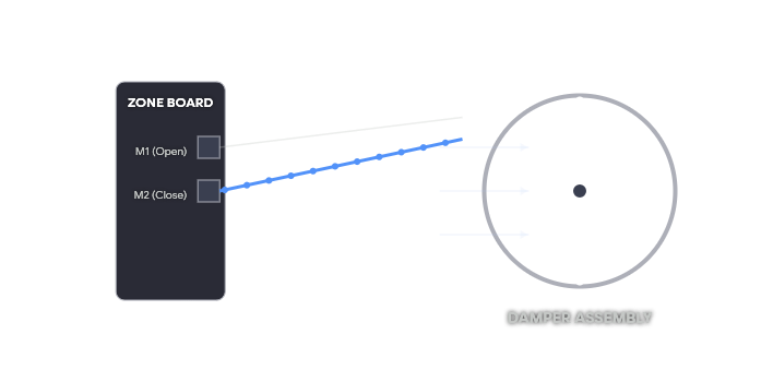
- Zoning Board Terminals — Shown on the left side of the diagram. These are labeled (example: M1, M2, M3 for each zone’s damper motor).
- Damper Motor Connections — Shown on the right side. Each damper has terminals for the wires coming from the zoning board.
- Wire Colors — Diagrams usually show recommended wire colors (though actual wire colors can vary).
- Transformer Connection — Shows where the 24V power supply connects to power the entire zoning system.
Technicians use these diagrams to trace wires, test voltage, and diagnose why a damper isn’t opening or closing correctly.
Common Zone Damper Wiring Mistakes
Incorrect wiring is one of the top reasons zoning systems don’t work properly. Common mistakes include:
- Swapping the open and close wires on a damper
- Not running a common (C) wire to the zoning board
- Using the wrong gauge wire, which causes voltage drop
- Connecting multiple dampers incorrectly on the same zone terminal
- Failing to install a bypass damper when required
Why Professional Wiring Is Important
While zone damper wiring diagrams look simple on paper, real-world installations often involve long wire runs, multiple dampers, and integration with existing HVAC equipment. A small wiring mistake can cause an entire zone to stop working or make the system run inefficiently.
At Only Way Air, our technicians are trained to read and follow manufacturer wiring diagrams precisely. We test every connection before leaving the job to make sure your zoning system works correctly from day one.
Frequently Asked Questions About Zone Damper Wiring
Can I install or repair zone damper wiring myself?
While the voltage is low (24V), zoning wiring requires proper knowledge of controls, dampers, and system design. Incorrect wiring can damage equipment or cause the system to fail. We strongly recommend professional service.
Do all zone dampers use the same wiring?
No. Different brands (Honeywell, EWC, ZoneFirst, etc.) use slightly different wiring methods. That’s why technicians always refer to the specific wiring diagram for the dampers installed in your home.
What happens if a damper wire breaks?
If a wire to a damper breaks, that zone will usually stay in one position (either always open or always closed) until the wire is repaired. This often causes temperature problems in that area of the home.
How do I know which wires go to which damper?
Technicians use the wiring diagram that came with your zoning system. They also test wires with a multimeter to confirm which wire controls which damper before making any changes.